UC San Diego
Designing a coflow burner for combustion research
Electromechanical Development Engineer · 2009–2011
Comparing how fuels burn requires controlled, repeatable starting conditions right at the burner. Supporting a $500,000 Air Force Research Laboratory grant for a low-flow liquid-fueled burner, I designed a custom coflow burner and its supporting rig in SOLIDWORKS, coordinated part fabrication with outside machine shops, and integrated the fuel and temperature controls.
In a coflow burner, a central stream of fuel and its surrounding air travel in the same direction—requiring smooth, even delivery while keeping the hardware accessible for adjustments between runs.
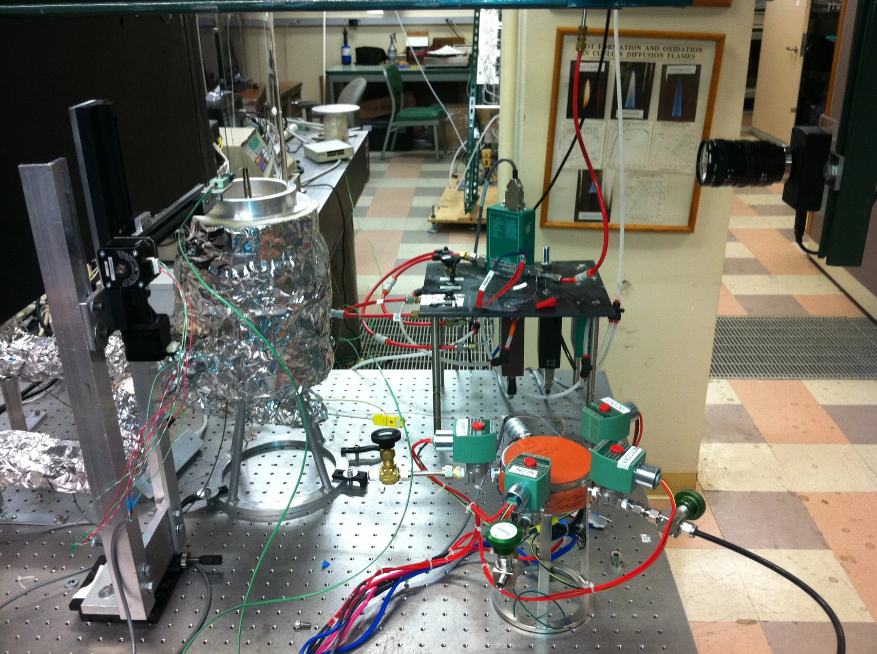 Enlarge imageEnlarge: Coflow experimental setup with burner, positioning mechanism, valves, tubing and camera.
Designing for fabrication and experimental use
I developed the mechanical design around how every component would be machined, assembled, and adjusted on the bench. Because the burner needed a smooth, uniform gas flow, I worked with suppliers to source a honeycomb insert material capable of straightening the flow while withstanding heat near the flame.
Outside machine shops fabricated the machined parts to my drawings, and I assembled and integrated the burner hardware with its flow and temperature controls.
Vaporizing fuel at very low flow rates
Liquid fuel delivery posed a distinct physics challenge: we needed to supply JP-10 jet fuel at very low flow rates, where vaporizing liquid smoothly is difficult. After testing several approaches, I selected an ultrasonic transducer to atomize the liquid into a fine mist ahead of a heated chamber that vaporized it before reaching the burner.
Once vaporized, the fuel had to stay in vapor form all the way along the feed line: too little heat allowed droplets to condense, while too much heat broke down the fuel chemically before it reached the flame. Integrating the ultrasonic vaporizer, heated transfer lines, closed-loop temperature controls, and metered gas flows gave researchers clean, repeatable starting conditions for every experiment.
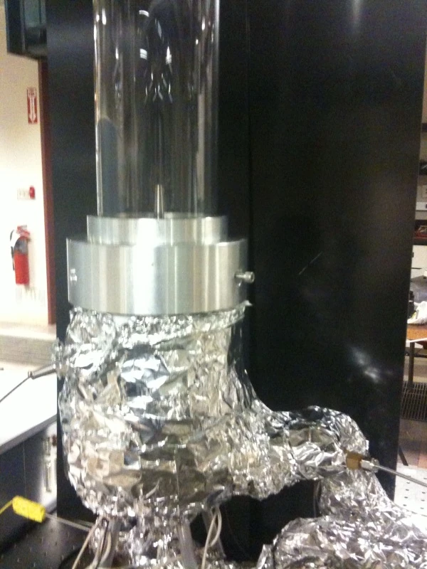 Enlarge imageEnlarge: Coflow burner body with a glass chimney and insulated heated connections.
Studying flame shape, lift-off, and blowout
Experiments on this apparatus mapped how a flame changed shape, lifted away from the burner rim, or blew out entirely as fuel and airflow conditions shifted—supporting published investigations of flame structure and blowout limits.
Positioning probes and collecting measurements
Alongside designing the burner and fuel-delivery hardware, I automated spatial probe measurements on the coflow setup as part of my wider LabVIEW automation effort across the laboratory’s experimental rigs.
Experience used here
CAD · SOLIDWORKS · Mechanical design · Design for manufacture · Fabrication coordination · Fuel handling · Temperature control · Grant management